|
|
|
Prepping the EL wire
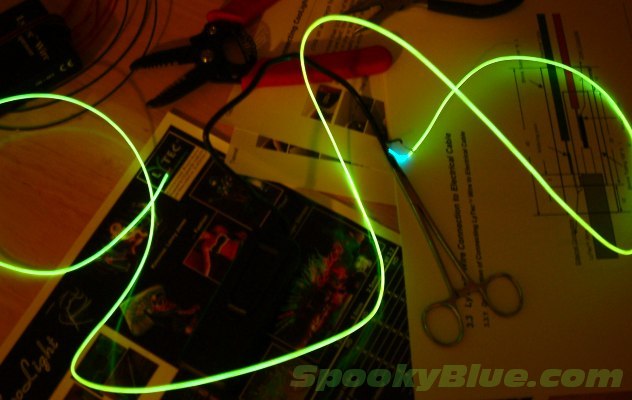
Electro luminescent wire is cool. When lit, it wouldn't really look out of place enveloping a somewhat pudgy guy in long underwear attending a TRON convention. But before power can be applied, the wire must be prepped. The ends must be stripped, and one end must be terminated.
I won't sugarcoat it. This part of the project is a pain in the ass. I don't know who came up with the idea of manufacturing the EL conductor wires to about the size of a HUMAN HAIR, but that's the case. Stripping and prepping the ends is tricky and requires a fine touch. You'll need a good pair of wire strippers. A medicinal highball isn't out of the question either.
|
|
|
|
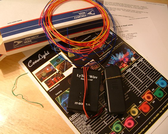
Our package from Coolight arrived in about 7 days containing our 20ft of EL wire, 3V inverter, sequencer, and a slick looking brochure advertising other Coolight products.
What was noticeably missing was any type of instructions. I could make a protracted editorial comment regarding the general sad state of product support. However, that's not a very constructive use of this space. Instead, here's a note about safety...
A note about safety
Don't just jump in and start playing tricks with that neat inverter you just bought. It's very unlikely that it will kill you, but you can still get a nasty burn. So keep it out of your mouth, don't stick the ends in your ears, and refrain from carrying it around in your pocket with the power turned on. That "is this an inverter in my pocket, or am I just happy to see you" joke isn't funny.
|
|
EL wire-ology
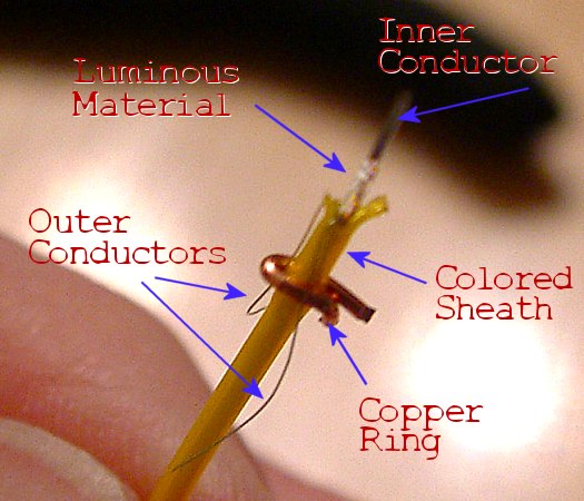
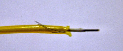
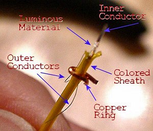
EL wire is essentially a capacitor. There is a stiff inner electrode surrounded by a coating of light emitting phosphors. Around this is wrapped two very very thin electrodes. These wrapped electrodes are the same point electrically because of a very thin conductive film coating the surface of the light emitting phosphors.
The whole package is covered by an insulating colored sheath. The light emitting phosphors glow when an alternating current is applied across the two electrodes. EL wire will not light if a DC current is applied. Energy is delivered to the light emitting phosphors via the varying electric field that rises and collapses through it when as little as 100V AC is applied across the inner and outer electrodes. The higher the frequency, the brighter the wire glows. The light emitting phosphors actually only glow one color, which is a sort of pale aqua. The plastic sheath is what gives EL wire its different colors.
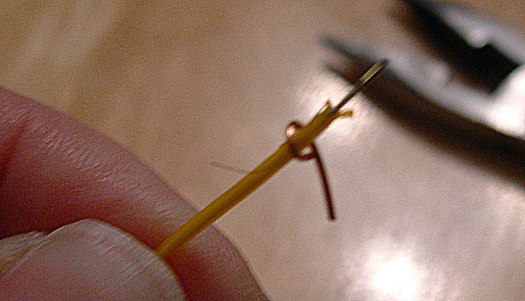
Let me say once again that the hair-thin outer electrodes are very fragile. You'll see what I mean when you try to strip your first EL wire. Buy more than you need.
In this photo you'll notice the "copper ring" wrapped around the two peeled back outer electrodes. This is my addition, and it will enable us to connect the power source. More about this in a minute. |
 |
Termination
It's necessary to properly terminate the end of the wire opposite that connected to the power source. This is an important step to ensure there are no shorts. Try hooking up your wire without terminating the other end and it'll probably work just fine. That is, until you've spent an hour or two bending the thing around an armature, then power it up and nothing happens. You'll remember what I said and you'll cuss as loud as I did. Terminate the other end!
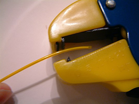
1 - Carefully strip away about an inch of the plastic sheath. I hope you bought more wire than you really need because you'll probably whittle this thing down an inch at a time every time you pull out one of those wire-hair-electrode things and have to start again.
2 - Bend the two outer electrodes back and over the colored sheath. Using a razor blade, scrape off a half inch of luminous material from the inner conductor. The idea is to isolate the inner electrode from the outer. Make sure they aren't touching.
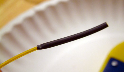
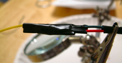
3 - Install a length of heat shrink tubing, completely covering the exposed wires and extending another half inch or so beyond the end. Do not linger with the heat gun when you heat the tubing. Use just enough to seal it or you'll melt the plastic sheath. (Sigh, but I learned) |
|
|
|
|
Connecting the power leads
Note: Don't make your solder connections until after you have finished mounting the el-wire shapes in the display case. It's okay to test your connections at this point using alligator clips, but leave the ends free. You'll see why in the next secion (Mounting & Finish Out).
After terminating the end of your EL wire, you'll want to hook up the other end to the inverter. Strip the end just as before, but this time leave yourself an inch or so of exposed inner electrode to attach your power lead to. Make sure to scrape all the luminous material from the area to be soldered. Now, those two tiny little wires... Unless you're really good with a soldering iron, and you have a micro-tip, you'll need to fashion some kind of wrap to solder the other lead to. One website I found suggested using copper tape. I couldn't find anything like what they described, so I came up with this little trick.
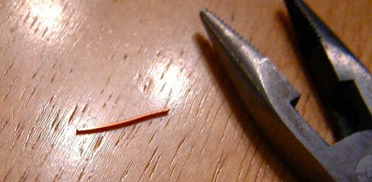
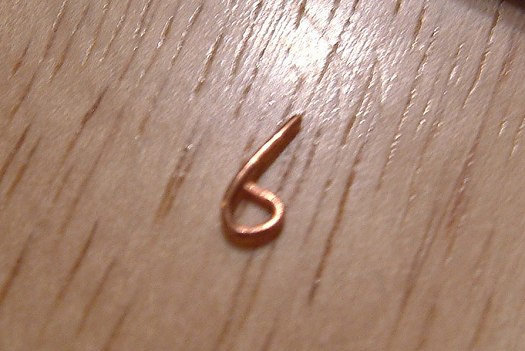
Strip the insulation off a short length of solid copper wire (preferably 12 or 14 gauge), and cut it to about 1.5" long. Using needle nose pliers, fashion a loop. Bend back the two hair-thin wires and slide the loop over them. Make sure the inner and outer electrodes aren't touching (it's okay if the hair-thin electrodes touch). Now firmly crimp the loop down. Don't crush the EL wire. Only apply enough pressure so the loop doesn't move, and make sure both wires are held in place. Snip off the excess copper wire, and now you have a handy solder point.
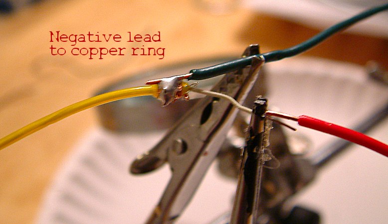
Test your electrical connections before soldering. Using alligator clips, connect the black inverter lead to the copper ring and the red lead to the inner electrode. Turn on the inverter. If nothing happens, make sure the two leads aren't touching. If still nothing happens, make sure the end of the inner electrode is free of luminous material. If nothing continues to happen, resist the desire to open a window and chuck the whole thing into the yard. Instead, make sure those damn tiny outer electrodes aren't broken. Sometimes it's just a good idea to snip the end off and start over. Oh yeah, those batteries you're using are good, aren't they? |
|
|
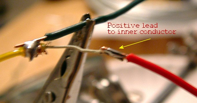
| If everything worked, the wire should light up. You may also notice a faint, high-pitched whine. This is normal. What you're hearing is the AC doing its thing exciting all those phosphors. Disconnect the power and solder the negative lead to the copper ring, the positive lead to the inner electrode, and wrap the connections in electrical tape. When making your connections, make sure to keep the two leads far enough away from each other that there's no chance they'll come together and short. Note how much of the plastic sheath I removed for the connection below. |
|
|
|
|
| You're going to have to excuse the poor picture quality of these extreme closeups. You're lucky I took the time to stop every few minutes and snap a photo. Otherwise you probably would have lost interest about 10 paragraphs back and be surfing for pr0n right now. |
|
|
|